Slot Waveguide Mode
Metal pipe waveguides are often used to guide electromagnetic waves.The most common waveguides have rectangular cross-sections and so arewell suited for the exploration of electrodynamic fields that dependon three dimensions. Although we confine ourselves to a rectangularcross-section and hence Cartesian coordinates, the classification ofwaveguide modes and the general approach used here are equallyapplicable to other geometries, for example to waveguidesof circular cross-section.
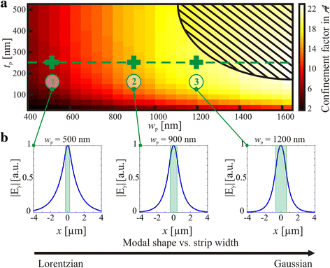
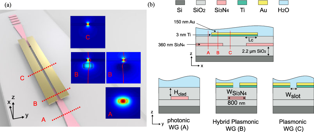
A slot waveguide is a well known optical waveguide, formed by two high refractive index photonic wires very close to each other, surrounded by a low refractive index medium. The former two types of plasmonic slot waveguides often support guided modes, while the latter air–SiO 2 asymmetric waveguide supports leaky modes above the cutoff slot width or film thickness.29,32 For realizing effective E/O modulation, it is crucial to have a large modulation depth, while keeping the insertion loss as low as possible. Waveguide with a slot width as large as 320nm. This strip-to-slot mode converter is optimized to provide a measured insertion loss as low as 0.08dB. Our mode converter provides 0.1dB lower loss compared to a conventional V-shape mode converter. This mode converter is used to couple light into and out of a 320nm slot photonic crystal waveguide.
The parallel plate system considered in the previous threesections illustrates much of what can be expected in pipe waveguides.However, unlike the parallel plates, which can support TEM modes aswell as higher-order TE modes and TM modes, the pipe cannot transmit aTEM mode. From the parallel plate system, we expect that a waveguidewill support propagating modes only if the frequency is highenough to make the greater interior cross-sectional dimension of thepipe greater than a free space half-wavelength. Thus, we will findthat a guide having a larger dimension greater than 5 cm wouldtypically be used to guide energy having a frequency of 3 GHz.
We found it convenient to classify two-dimensional fields astransverse magnetic (TM) or transverse electric (TE) according to whether E or H was transverse to the direction ofpropagation (or decay). Here, where we deal with three-dimensionalfields, it will be convenient to classify fields according to whetherthey have E or H transverse to the axial direction ofthe guide. This classification is used regardless of thecross-sectional geometry of the pipe. We choose again the ycoordinate as the axis of the guide, as shown in Fig. 13.4.1. If wefocus on solutions to Maxwell's equations taking the form
then all of the other complex amplitude field components can bewritten in terms of the complex amplitudes of these axial fields,Hy and Ey. This can be seen from substituting fields having theform of (1) and (2) into the transverse components of Ampère'slaw, (12.0.8),
Slab Waveguide Mode Calculator
and into the transverse components of Faraday's law, (12.0.9),

If we take y and y as specified, (3) and(6) constitute two algebraic equations in the unknowns xand z. Thus, they can be solved for these components.Similarly, x and z follow from (4) and (5).
We have found that the three-dimensional fields are asuperposition of those associated with Ey (so that the magneticfield is transverse to the guide axis ), the TM fields, and those dueto Hy, the TE modes. The axial field components now play the roleof 'potentials' from which the other field components can be derived.
We can use the y components of the laws of Ampère andFaraday together with Gauss' law and the divergence law for H toshow that the axial complex amplitudes y and ysatisfy the two-dimensional Helmholtz equations.
TM Modes(Hy = 0):
where
and
TE Modes(Ey = 0):
where
These relations also follow from substitution of (1) and (2) into they components of (13.0.2) and (13.0.1).
The solutions to (11) and (12) must satisfy boundary conditions onthe perfectly conducting walls. Because Ey is parallel to theperfectly conducting walls, it must be zero there.

TM Modes:
The boundary condition on Hy follows from (9) and (10), whichexpress x and z in terms of y. On the walls at x = 0 and x = a, z = 0. On the wallsat z = 0, z = w, x = 0. Therefore, from (9) and(10) we obtain
TE Modes:
The derivative of y with respect to a coordinateperpendicular to the boundary must be zero.
The solution to the Helmholtz equation, (11) or (12), follows apattern that is familiar from that used for Laplace's equation in Sec.5.4. Either of the complex amplitudes representing the axial fields isrepresented by a product solution.
Substitution into (11) or (12) and separation of variables then gives
where
Solutions that satisfy the TM boundary conditions, (13), are then
TM Modes:
so that
When either m or n is zero, the field is zero, and thus m and nmust be equal to an integer equal to or greater than one. For a givenfrequency and mode number (m, n), the wave number ky isfound by using (19) in the definition of p associated with (11)
with
Thus, the TM solutions are
For the TE modes, (14) provides the boundary conditions, and we areled to the solutions
TE Modes:
Substitution of m and n into (17) therefore gives
The wave number ky is obtained using this eigenvalue in thedefinition of q associated with (12). With the understanding thateither m or n can now be zero, the expression is the same as thatfor the TM modes, (20). However, both m and n cannot be zero. Ifthey were, it follows from (22) that the axial H would be uniformover any given cross-section of the guide. The integral of Faraday'slaw over the cross-section of the guide, with the enclosing contour Cadjacent to the perfectly conducting boundaries as shown in Fig.13.4.2, requires that

where A is the cross-sectional area of the guide. Because the contouron the left is adjacent to the perfectly conducting boundaries, theline integral of E must be zero. It follows that for the m =0, n = 0 mode, Hy = 0. If there were such a mode, it wouldhave both E and H transverse to the guide axis. We willshow in Sec. 14.2, where TEM modes are considered in general, thatTEM modes cannot exist within a perfectly conducting pipe.
Even though the dispersion equations for the TM and TE modes onlydiffer in the allowed lowest values of (m, n), the field distributionsof these modes are very different.
9 In other geometries,such as a circular waveguide, this coincidence of pmn andqmn is not found.The superposition of TE modes gives
where m n 0. The frequency at which a given modeswitches from evanescence to propagation is an important parameter.This cutoff frequency follows from (20) as
TM Modes:
TE Modes:
Rearranging this expression gives the normalized cutoff frequency asfunctions of the aspect ratio a/w of the guide.
These normalized cutoff frequencies are shown as functions of w/ain Fig. 13.4.3.
Slot Waveguide Modulator
The numbering of the modes is standardized. The dimension w ischosen as w a, and the first index m gives the variation ofthe field along a. The TE10 mode then has the lowest cutofffrequency and is called the dominant mode. All other modeshave higher cutoff frequencies (except, of course, in the case of thesquare cross-section for which TE01 has the same cutofffrequency). Guides are usually designed so that at the frequency ofoperation only the dominant mode is propagating, while allhigher-order modes are 'cutoff.'
In general, an excitation of the guide at a cross-section y =constant excites all waveguide modes. The modes with cutoff frequencies higher than the frequencyof excitation decay away from the source. Only the dominant mode hasa sinusoidal dependence upon y and thus possesses fields thatare periodic in y and 'dominate' the field pattern far away fromthe source, at distances larger than the transverse dimensions of thewaveguide.
Example 13.4.1. TE10 Standing Wave Fields
The section of rectangular guide shown in Fig. 13.4.4 is excitedsomewhere to the right of y = 0 and shorted by a conducting plate in theplane y = 0. We presume that the frequency is above the cutofffrequency for the TE10 mode and that a > w as shown. Thefrequency of excitation is chosen to be below the cutoff frequencyfor all higher order modes and the source is far away from y = 0(i.e., at y a). The field in the guide is then that of theTE10 mode. Thus, Hy is given by (25) with m = 1 andn = 0. What is the space-time dependence of the standing wavesthat result from having shorted the guide?

Because of the short, Ez (x, y = 0, z) = 0. In order to relate thecoefficients C+10 and C-10, we must determine zfrom y as given by (25) using (10)
and because z = 0 at the short, it follows that
so that
and this is the only component of the electric field in this mode. We can now use (29) to evaluate (25).
In using (7) to evaluate the other component of H, remember thatin the C+mn term of (25), ky = mn, while in theC-mn term, ky = -mn.
To sketch these fields in the neighborhood of the short anddeduce the associated surface charge and current densities, considerC+10 to be real. The j in (31) and (32) shows that Hx andHy are 90 degrees out of phase with the electricfield. Thus, in the field sketches of Fig. 13.4.4, E andH are shown at different instants of time, say E when t = and H when t = /2. The surfacecharge density is where Ez terminates and originates on the upper and lowerwalls. The surface current density can be inferred from Ampère'scontinuity condition. The temporal oscillations of these fieldsshould be pictured with H equal to zero when E peaks, andwith E equal to zero when H peaks. At planes spaced bymultiples of a half-wavelength along the y axis, E is alwayszero.
The following demonstration illustrates how a movable probe designedto couple to the electric field is introduced into a waveguide withminimal disturbance of the wall currents.
Demonstration 13.4.1. Probing the TE10Mode.
A waveguide slotted line is shown in Fig. 13.4.5. Here theline is shorted at y = 0 and excited at the right. The probeused to excite the guide is of the capacitive type, positioned sothat charges induced on its tip couple to the lines of electric fieldshown in Fig. 13.4.4. This electrical coupling is an alternative tothe magnetic coupling used for the TE mode in Demonstration 13.3.2.

The y dependence of the field pattern is detected in theapparatus shown in Fig. 13.4.5 by means of a second capacitiveelectrode introduced through a slot so that it can be moved in they direction and not perturb the field, i.e., the wall is cut along the lines of the surface current K. From the sketch of K given in Fig. 13.4.4, it can be seen that K is inthe y direction along the center line of the guide.
The probe can be used to measure the wavelength 2 /ky of the standing waves by measuring the distance between nulls in theoutput signal (between nulls in Ez). With the frequency somewhatbelow the cutoff of the TE10 mode, the spatial decay away fromthe source of the evanescent wave also can be detected.